Vacuum Release (VR) Tray User Guide
Application Note
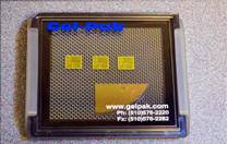
Gel-Pak Vacuum Release™ (VR Series) Tray are “pocketless” carriers which hold devices securely in place during shipping or handling, and offer the unique ability to release the devices on demand for unloading. Use the recommended process parameters and procedures below for best device handling results.
A fully interactive “Product Selection Wizard (PSW) Program” is available on the Gel-Pak website which will suggest a complete Gel-Pak part number based on the application details entered by the user.
Section 1: Overview
The Vacuum Release technology relies on temporarily changing the surface contact area between the device and the VR tray elastic Gel membrane placed over a mesh material. This change in surface contact directly affects the magnitude of the Gel holding force.
In the normal “Hold Mode” (Figure 1), the surface contact is maximized and devices are held firmly in place for shipping, handling, and storage.
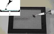
In the temporary “Release Mode” (Figure 2), the surface contact is minimized by applying vacuum thru a hole in the underside of the tray which causes the Gel membrane to conform to the shape of the mesh. This reduces the holding force between the Gel and device (fewer points of contact) which allows for easy device removal using a vacuum pick-up tool.
Once vacuum is removed, the elastic Gel membrane returns back to its original position and securely hold the remaining devices. The VR trays are reusable therefore this Hold and Release process can be done repeatedly on the same VR tray.
Please note that applying vacuum to underside of tray is only required during the actual device unloading process. Vacuum is not used when loading devices on Gel surface.
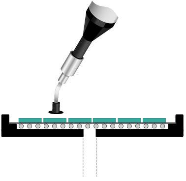
Figure 1: Hold Mode
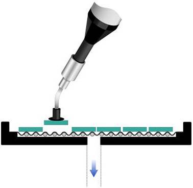
Figure 2: Release Mode
Section 2: Recommended Mesh Geometry
The correct Mesh Geometry (also referred to as Mesh Size) for a specific device is based on the device X,Y dimensions. For optimal device unload performance, the goal is to minimize the number of Gel-to-Device contact points when the VR Tray is in Release Mode (Figure 2). Therefore, Gel-Pak offers a range of different mesh geometries: 16, 33, 76, 103, 137, 195, NDT (Figure 3). Each mesh size number corresponds to the number of thread lines per linear inch. If the device is smaller than 254um x 254um, refer to special NDT product page on the Gel-Pak website.
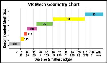
Figure 3: Mesh Chart
The mesh size with the largest spacing between each thread line results in the fewest contact points for a given device size when the tray is in Release Mode. In Figure 3 above this corresponds to the size 16 mesh. In contrast, the mesh with the least amount of spacing between thread lines (size 195 mesh) results in largest number of contact points for a given device size while in Release Mode.
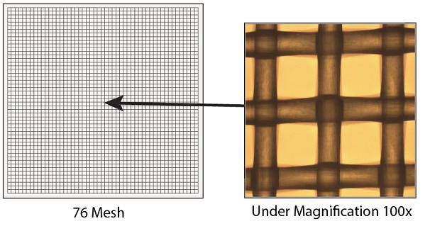
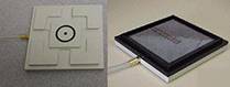
Figure 4: Mesh Photo
Since fewer points of contact equals less Gel holding force, the goal when selecting the mesh geometry is to use the mesh with the fewest number of threads lines as possible while still keeping the device fully supported while in Release Mode. An insufficient number of mesh contact points for a given device size will cause the device to tilt when vacuum is applied to the tray which could result in unload (mis-pick) issues.
It is important to note that Mesh Size only affects the device unload performance and only when the VR tray is in Release Mode (Figure 2). Mesh Size has no effect when the VR Tray is in its normal Hold Mode (Figure 1). The Gel holding force (Section 5) during shipping and handling is completely unrelated to the Mesh Size.
The recommended Mesh Geometry based on device size can be easily determined using Figure 3 above or Table 1 below.
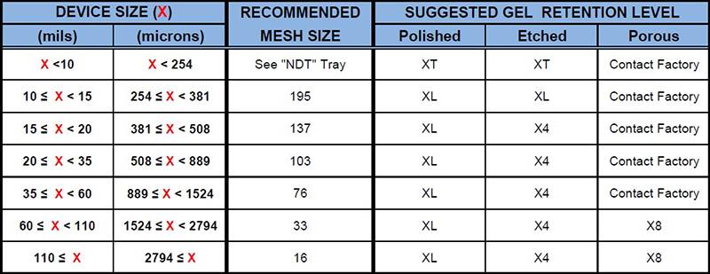
Table 1: Recommended Mesh and Gel Retention Level
Notes:
a) X = Smaller side dimension (example: for a 15 x 10 mil die, reference will be 10 mils)
b) For “borderline” die sizes, evaluation of both upper and lower mesh types is recommended
c) For high aspect ratio devices, more than one mesh size may need to be evaluated
d) If device is less than 254um x 254um, refer to special NDT product page on the Gel-Pak website
Gel-Pak also offers an online program that will calculate the recommended mesh size for your device type, along with the maximum number of devices stored per tray. The number of devices per tray is dependent on tray size, device size, and desired spacing.
Section 3: Suggested Gel Retention Level (Holding Force)
The required Gel Retention Level (Xn) for a specific device is a function of properties such as dimensions, backside surface roughness, flatness, and material coating. Table 1 above also contains the suggested Retention Levels (also referred to as Tack Levels) based on the surface roughness and dimensions.
Determining the correct Gel Retention Level for a specific device is not an exact science. Each device has its own unique properties therefore the tack level can only be “suggested”. It is strongly recommended that VR samples be evaluated to ensure that the correct tack level is selected.
The Gel Tack level must be high enough to securely hold the device during shipping and handling, yet allow the device to be easily unloaded while tray is in Release Mode. The tendency is to want to select the highest tack level in order to obtain the maximum holding force, but this can result in device unload issues (excessive holding force) The optimum Gel Retention Level is a balance between both device holding and unload performance.
Sections 5 and 7 describe how to evaluate if the correct Gel Retention Level and Mesh Size have been selected used for a specific device.
Section 4: Device Loading Instructions
Load device on the Gel surface using standard production methods. Typical manual systems utilize tweezers or a vacuum pick-up tool while automated systems employ a vacuum tip/collet. Take care when using tweezers not to puncture the Gel membrane.
When possible, slight downforce should be applied to the device to initiate good surface contact with the Gel. Device should typically be mounted on Gel for minimum of 1 minute to achieve sufficient surface contact before transporting. (Exact required time will vary based on device surface roughness, mass, and Gel retention).
Section 5: Gel Holding Force Test
In order to verify that a selected Gel Tack level is sufficient for the loaded device, close the Gel-Pak Carrier and tap the corner on a hard surface. Tap as hard as needed to evaluate Gel holding strength. Tap testing will simulate the Gel’s ability to effectively hold a device during typical shipping and handling environments. A more severe drop test (1 meter) can be performed after the device has been loaded on Gel surface for several minutes.
If any device shift position during testing, either allow a longer waiting period for increased Gel contact area (holding strength) prior to transporting or evaluate a higher Gel Retention Level as needed. For large mass devices, it is recommended that the Gel carrier be placed in an upside down position for 24 hours to confirm that the device does not pull away from the Gel due to gravity.
Section 6: Device Unload Instructions (VR-44 example)
1. Slide off the Clip and remove the Lid from the VR Tray. (For 2” VR trays in hinged boxes or Large Format VR plates, remove tray from box)
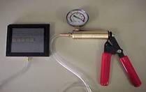
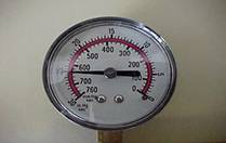
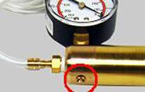
2. Place the VR Tray on a Vacuum Plate (VHP-24 Hand Pump shown in photo). VR Trays are also fully compatible with Manual, Semi-automatic or Automated device handling equipment.
3. Make sure the Tray is aligned with the vacuum plate o-ring to obtain a tight backside seal and hold vacuum.
4. Apply 25" Hg of vacuum. This will put the VR Tray into "Release Mode" and allow devices to be easily unloaded.
5. While in "Release Mode," carefully remove the devices using a vacuum pick-up tool.
6. After removing the selected devices from the Gel surface, release the vacuum. (Press the pin on VHP-24 as shown in photo to remove vacuum)
7. Place the Lid and Clip back on the VR Tray and store for future use. (For 2” VR trays in hinged boxes or Large Format VR plates, place tray back inside box).
Note: It is not necessary to remove all devices from Tray. VR Trays are reusable.
Section 7: Device Unload Evaluation Test
For best unload results apply 25” Hg of vacuum to backside of the VR tray to put into Release Mode. The Gel membrane may appear to be in the release mode under relatively low vacuum conditions, but full vacuum is recommended for optimal device release.
Unload the device simulating the actual production environment: dull-tip tweezers, manual vacuum pick-up tool, or automated die handling equipment. Take care to ensure the vacuum pick-up tip parameters are compatible with the specific device size and material. For automated equipment, set-up adjustments such as pick-up speed might be required to optimize the unload process.
The pick-up tools overdrive (contact downforce) during unload should be minimized to prevent the device from being driven or pushed into the Gel surface. This can damage your device and/or cause increased device unload forces. Tweezers can be used if needed, but are not recommended as they can puncture the Gel membrane if used incorrectly. Pick-up tools with continuous vacuum supply are recommended when available.
If the device is difficult to unload from the Gel surface, confirm that the correct mesh size is being used (see Section 2). Using a tighter than needed mesh geometry will result in excessive points of contact that can substantially increase the required unload force.
If mesh size is correct, repeat unload test using a lower Gel Retention Level. Make sure to also repeat the Gel Holding Force Test (Section 4) if a lower Tack Level is selected.
For all products, a longer-term storage test should be performed by leaving device on the Gel for a minimum of 48 hours to achieve maximum surface contact prior to unloading.
Section 8: VR Accessories
Refer to the Gel-Pak website for a summary of all VR accessories.